
by Erich Weidenhammer
[Update 20/03/2013] Part 2: “The Afterlife of a Scientific Instrument”
Part 1: Descripton, Operation, Development
At some point in the past several decades, the Institute for the History and Philosophy of Science and Technology (IHPST) inherited a number of items from the dispersed Canadian Museum of Health and Medicine collection. Among these was a lacquered black box containing the critical components of a Chamber’s Micromanipulator. This instrument was developed by the American biologist Dr. Robert Chambers (1881-1957) during his time at Cornell University Medical College. It was first described in publication in 1918 and was commercialized by the Leitz company in the mid-1920s. The U of T ‘s example was most likely purchased for the recently-founded School of Hygiene in the late 1920s or 1930s.
This instrument is a rare treasure. It is the only medical research instrument from that period currently in the UTSIC collection. I haven’t yet found another surviving example (If you know of one, please let me know.) Its design reveals the aesthetics, as well as the technological constraints, of its time and place. Its essential feature is a precise mechanism based on hinged steel bars actuated by adjusting screws.
Through this simple mechanism, Chambers’ instrument made it possible to precisely manipulate microscopic objects—notably living cells—at the physical limits of optical magnification. In a sense, the micromanipulator can be seen as a refinement of the dissecting microscope as it basically consists of a steady platform, tools, and magnifying optics. To manipulate material at the cellular level, however, requires a special mechanism (a “mechanical hand”) to manoeuvre specialized ‘microtools’ such as microneedles and micropipettes. [1. Hildebrand (1960), p. 280.] Though we take such instruments for granted today, their development gave researchers a much greater ability to ‘see’ the physical structure of microscopic objects. The practice of using of the micromanipulator was deemed significant enough to be named ‘micrurgy’ by the Hungarian researcher Tibor Péterfi in 1923.
In his 1983 book Representing and Intervening, philosopher of science Ian Hacking pointed out that we interpret what we see through a microscope by the active process of ‘doing.’ Rather than passively receiving self-evident information through the eyepiece, we actively learn to see through countless interventions—the development and application of dyes and fixatives, the use and improvement of various optical systems, the mastery of the Microscope’s various controls. This process of removing flaws and resolving ambiguities is what permits us to reconcile our understanding of the physical world with the signal emerging from the microscope. [2. Hacking (1983), pp. 189-192.]
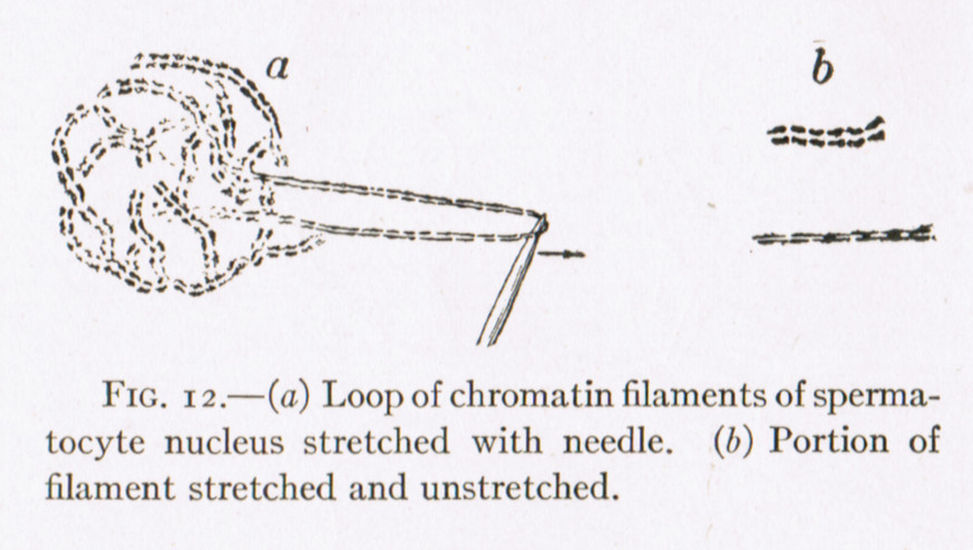
Hacking’s insight is worth keeping in mind when considering the micromanipulator. Injuring, stretching, injecting, or tearing apart a cell and removing its parts, provided an important way to investigate issues such as the circulation and viscosity of the cytoplasm at various stages of development, the physical properties of cellular structures such as chromosomes, the process of fertilization, or the chemical workings of cell metabolism. Chambers spent his career intervening in the processes of living cells and writing about his findings. Other micrurgists did similar work with both living and non-living microscopic material. Their work clarified what was seen by microscopists. Like Chambers, they continually invented new tools to further their research. Some developed appendages to Chambers’ instrument. Some created new micromanipulators.
Background
The technology behind the micromanipulator began to develop in 1859 when the American doctor H. D. Schmidt created an instrument that clipped to a microscope stage which was capable of tearing apart individual cells. [3. Chambers (1918), pp 121-122.] In 1904, Dr. Marshall A. Barber of the University of Kansas introduced the ‘Hanging drop’ moist chamber—a glass box roofed over by a cover slip. Living cells were suspended in a droplet of liquid hanging from the roof of the chamber for manipulation under the microscope objective. The box was open on one end to permit the entry of microtools ending in curving tips which operated upwards against this coverslip roof (see fig. 9 .) This allowed researchers to maintain a microclimate necessary to sustain cellular samples for a useful length of time. In 1907, Barber developed an instrument that used rack and pinion mechanisms to move a micropipette in three axes. This was the first micromanipulator mechanism to develop a community of users. [4. Hildebrand (1960), pp. 280-281.] Barber’s moist chamber and micromanipulator introduced a workable technology for the manipulation of individual cells.
Chambers used Barber’s device in his early research and would have been deeply familiar with it. [5. Hildebrand (1960), p. 281.] His own design borrowed a great deal from it—notably the moist chamber—while solving its major deficiencies, especially mechanical problems such as ‘lost motion’ and ‘backlash’ to which the rack and pinion mechanism was subject. These occur as a result of flexibility, wear, and loose tolerance in a mechanism which prevent it from responding accurately to control inputs. The microscopic movements of a practical micromanipulator demand a very precise control system.

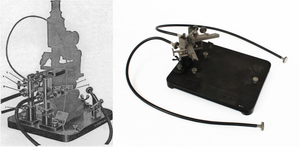
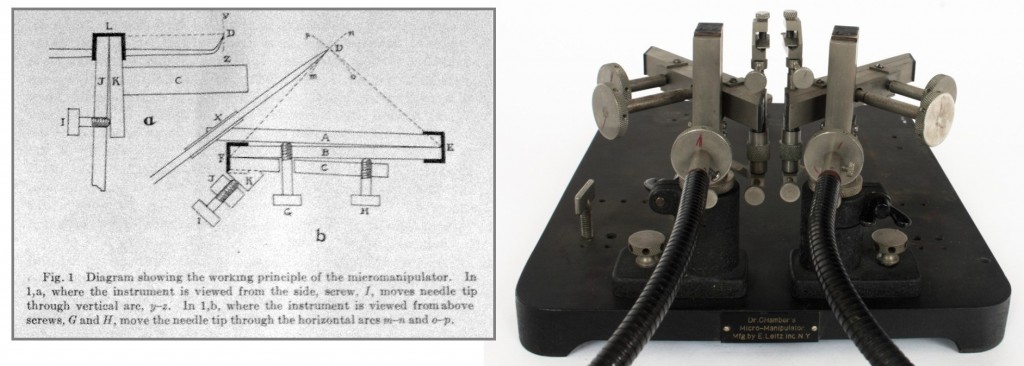
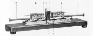
Chambers addressed this problem in a clever way. His micromanipulator used adjusting screws to force apart steel bars connected at one end with hinge/ springs of resilient metal (parts E, F & L in fig. 2 above.) This arrangement controlled the movement of the microtool effectively enough to be developed into a high-end commercial laboratory instrument by the Leitz company.
The trade literature issued around the middle of the 1920s with the first production version of the Chambers’ Micromanipulator claimed that it was capable of impaling a single red blood cell (6-8μ or 0.006-8mm) with a glass needle. In 1927, the Leitz company in New York listed the price for a model with one manipulator mechanism for $100 US. A model with two mechanisms sold for $165 US. These values are $6,030 and $9,940 respectively in 2011 US dollars relative to average American income. [6. measuring worth.con]
Forty years after it was first introduced, the Chambers’ Micromanipulator was still regarded as the most precise instrument available, though there were, by then, many alternatives. [7. Hildebrand (1960), p. 281, Chambers and Kopac, (1950), pp. 494-504.] While practically obsolete due to the labour and skill it required, it had long been established as an adaptable platform suitable to a range of scientific disciplines.
The Micromanipulator’s Essential Components
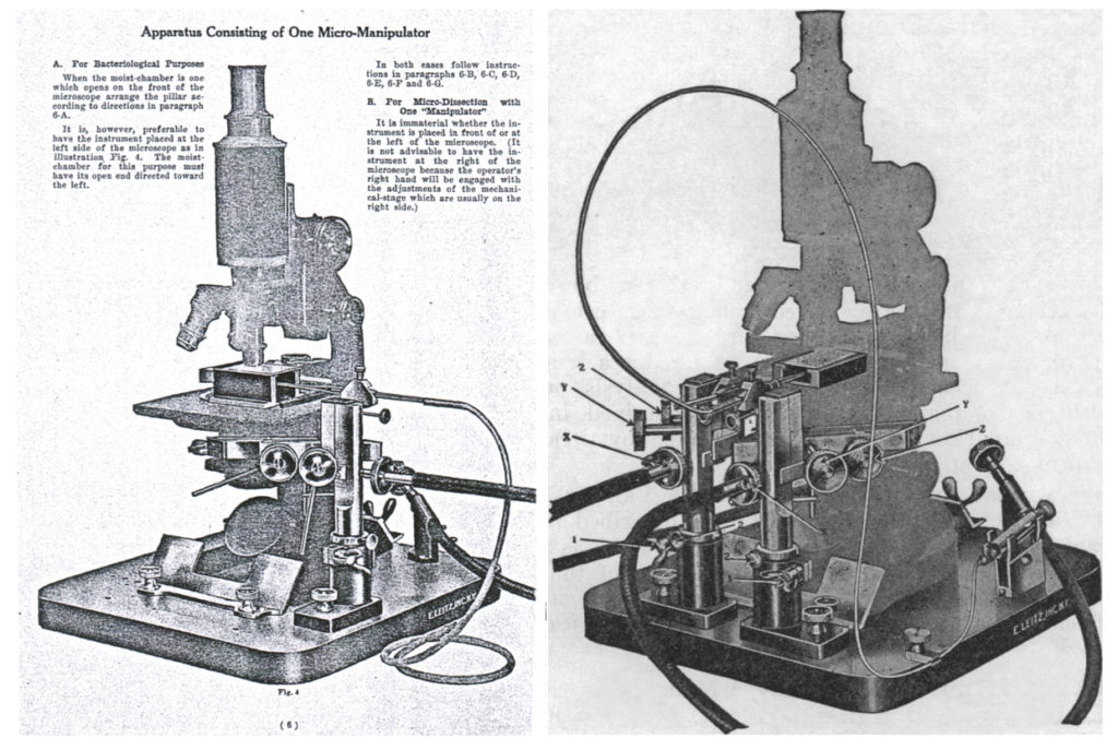
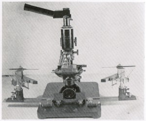
The ‘mature’ instrument produced by the Leitz Company consisted of a base and at least one micromanipulator pillar (also called ‘movements’.) The base was a solid steel platform onto which both the microscope and the micromanipulator pillars were secured. Screw holes provided multiple points of attachment for the pillars, either at the front or the sides. The side positions were generally used for isolating bacteria while the front positions were used for critical work. The base of the microscope was secured to the manipulator base using two adjustable steel clamps.
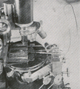
Each pillar consists of several of Chambers’ patented bar and hinge mechanisms so to as move a microtool along three axes. The microtool was clamped into a holder at the top of each pillar. When in use, the tool extended over the microscope stage into the moist chamber. Adjustment screws controlled the movement of the tool’s tip and allowed both the holder and the pillar itself to be adjusted vertically.
Pillars could be purchased singly or as a pair. One pillar was sufficient for picking up individual bacteria for cultivating pure strains, as well as for certain microdissection work such as embryology. For microinjection and for tissue cell dissection, two pillars were considered necessary. One illustration shows an instrument being used with four pillars—two at either side of the instrument [8. Chambers (1922b), p. 337.]
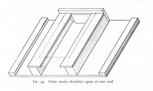
The moist chamber consisted of three glass or Bakelite walls glued to a thin glass slide around 50 x 75mm. The chamber opened at either the front or the side depending on where the micromanipulator pillars were mounted. The roof of the chamber was formed by a coverslip, kept in place by a small amount of Vaseline at its borders. The material to be manipulated was suspended in one or more liquid droplets hanging inside of the chamber on the underside of this cover slip. The moist chamber was clasped in a mechanical stage so that it could be adjusted in the x, y plane relative to the microscope objective.
The precise dimensions of the chamber would depend on its purpose. The taller the chamber, the more freedom one had to manoeuvre the delicate glass microtools. Isolation of pure strains of bacteria, for instance, could be accomplished using a relatively tall 20mm-high chamber that opened to the side. [9. Khan (1922), p. 346.] On the other hand, Critical work at higher magnifications required tightly concentrated light from the microscope condenser below the stage. This meant that a special, or modified, condenser had to be used with a chamber no taller than the limit of its focal range—usually around 8-10mm. [10. Chambers and Kopac, (1950), p. 510.]
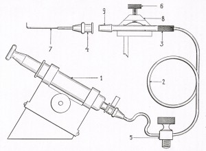
Microtools, usually made by the operator out of drawn glass tube or rod, were used to operate on individual cells under magnification. Microneedles (also called microscalpels) and micropipettes (also called microsyringes) were the most common. A microneedle was simply a glass tube or rod heated and pulled to produce a tool ending in a fine knife, or needle, point. A micropipette was made in a similar way but was always drawn from a tube. In Chambers’ system, the hollow tool was attached to a length of fine brass tube leading to a small Luer syringe that controlled the flow of liquid.
Glass has the advantage of producing a vanishingly fine point when made from a narrow rod or tube that is heated and drawn apart. It is also relatively inert—an important consideration when performing chemical experiments involving the microinjection of cells. It is , however, possible to use other materials. Wires made from certain metals may be given a fine point by dipping the tip in boiling acid or through electrolysis in order to create conductive microelectrodes . Historically, organic materials such as the scales of butterfly wings or the body hairs of a house fly have also been used. [11. Chambers and Kopac, (1950), pp. 522-523]
Setting-up and Operation
Using the micromanipulator required a range of laboratory skills. Much of the necessary instrumentation had to be prepared by the researcher, especially during the period before the instrument was commercialized around the middle of the 1920s. Literature on micromanipulators described how to make various pieces of necessary apparatus. This included instructions for building a simple microburner out of a bent piece of hard glass, secured to a block of wood and attached to a gas supply. This microburner would then provide the tiny heat source necessary to draw a fine pipette or rod into the finished tip needed for microtools.
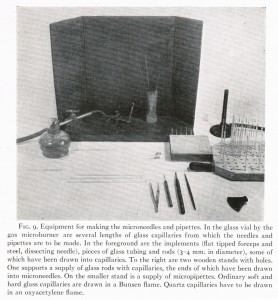
In order to make a micropipette, for instance, the operator would heat a thin glass tube over the flame of a bunsen burner before drawing it out into a delicate capillary between 0.3 and 0.5 mm in diameter. This fine capillary was then reheated over the smaller flame of a microburner. A gentle tug from a pair of fine forceps would separate the capillary into two tools ending in fine tips. The tips would then be reheated and bent upwards. Much practice was required to produce usable tips with consistency. Once attached to the microinjection apparatus, the micropipette was prepared just prior to operation by breaking off the very tip of the capillary against the roof of the moist chamber—a delicate operation. [12. Chambers (1922a), pp. 12-13. Chambers and Kopac (1950), pp. 513-520.]
The moist chamber was usually made in the laboratory as well. With the prepared chamber clasped in a mechanical stage and moist chamber slid backwards out of the way, the microtool(s) were secured in the holders and their tips brought into focus under a low magnification objective. Then the chamber was slid forward, the tips of the microtools lowered sufficiently to pass under its cover slip roof, and the droplet hanging from the cover slip roof brought into view. Manipulation could begin when both the material in the hanging droplet and the tips of the microtool(s) were brought into focus at the desired magnification. [13. Chambers and Kopac (1950), p. 521.]
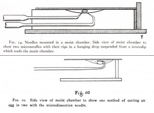
Different tasks required different arrangements of microtools. A single microneedle was sufficient for experimenting with local injury to a living cell. [14. Chambers (1922b), p. 338.] In this case, the x/y movement of the mechanical stage moved the sample against a stationary tool tip. Soft-ova and protozoa could be essentially pressed into two intact pieces against the cover slip using the tool’s curving tip. Other very soft-bodied cells such as unfertilized sea urchin eggs could be cut by drawing the tip of a microneedle downwards through the cell as it was held in place by the surface tension of the hanging drop. [15. Chambers (1922b), pp. 133-134]More complex operations such as pulling a starfish egg from its fertilization membrane required two microneedles. [16. Chambers (1921), p. 333.]
Often, a microneedle was used along with a micropipette and its associated microinjection equipment. Preparing this apparatus was a painstaking process in which it was first tested for leaks. When ready for use, the apparatus was completely filled with water except for a small portion of the tip of the micropipette containing the material to be injected. This system was quite versatile. One could use it to selectively remove parts of a living cell, or to inject various substances into the nucleus or cytoplasm for chemical tests. One micropipette could be used to gather a single bacterium in order to grow a pure strain.
Development and Commercialization
See: The Chambers’ Micromanipulator Evolves
It is possible to trace the evolution of Chambers’ micromanipulator using various published accounts beginning with Chambers’ first article on the subject in 1918. One sees it evolve from a simple mechanical device built in the laboratory workshop and relying on a great deal of hand-made apparatus, into a fully evolved commercial system presented in the Leitz trade literature. As the system became widely adopted, a number of specialized uses were developed and additional tools introduced.
Like many scientific instruments, Chambers’ instrument emerged from a collaboration between researchers and technicians. Early papers acknowledge the ‘skill and faithful workmanship’ of Mr. W. H. Farnmam, a mechanician at Columbia University who contributed to the ‘practical evolution’ of the instrument. [17. Chambers (1922), p. 3.] Other researchers, including Dr. H. B. Goodrich of Wesleyan University, duplicated it with the assistance of the University machine shop. Goodrich introduced a separate base onto which the micromanipulator mechanisms and the microscope could be independently attached. [18. Chambers (1918), pp. 125.]
At some point between 1918 and 1922, Chambers applied for a patent, which he received in 1926. The instrument became commercially available from the New York branch of the German Ernst Leitz company around this time. In his writing, Chambers thanked Ludwig Leitz (a grandson of the company’s founder), Henri Dumur, and Professor Max Berek for devoting their engineering resources to developing the instrument. [19. Chambers and Kopac (1950), p. 492.] These were all members of the company’s research and development team at its headquarters in Wetzlar, Germany. The speed at which Leitz modified the instrument and manufactured improvements for it as they were developed, shows the company’s close collaboration with researchers to satisfy the small market for this specialized material.
The product of this commercial engineering process was less a completed instrument than an adaptable system to be assembled from pre-manufactured parts depending on one’s purpose. Micromanipulator pillars could be purchased singly or in pairs and with or without the microinjection apparatus or the flexible shafts that moved the vertical controls conveniently to the front of the instrument. In addition to various components of the micromanipulator, microscopes, mechanical stages, and several condensers adapted to the longer working distances of the moist chamber were available for purchase along with related equipment such as microscope illuminators and rheostats. Essential components like the moist chamber and microburner, which were usually assembled in the lab, were sold alongside supplies such as tubing, cover glasses. One could furnish a lab with everything necessary to operate the instrument by ordering directly from Leitz.
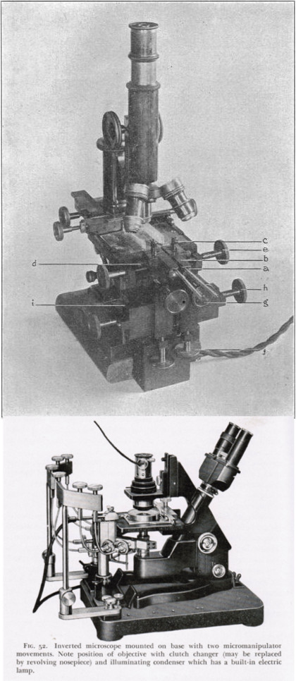
Later, Leitz offered specialized equipment such as a “machine for pulling microneedles and micropipettes”, introduced by Delafield Du Bois of New York University in 1931, and an inverted microscope that permitted the hanging droplet to be located on the floor, rather than the roof of the moist chamber.
An interesting comparison can be made between Chambers’ earlier descriptions of his shop-made instrument and the system described in the 1926 Leitz catalogue. In 1922, for instance, micropipettes were prepared by sealing a microtool made out of a short length of fine glass capillary or rod into a hand-made glass holder with sealing wax or De Kotinsky cement. On the opposite end, this glass holder had to be carefully attached to one end of a length of flexible brass tube leading athe Luer syringe. The syringe was mounted in place using a larger bent piece of brass tubing clamped to the micromanipulator base. If the delicate micropipette was accidentally broken or otherwise required changing, the seal had to be remelted. The entire system, with its multiple glue joints, was subject to leaks.
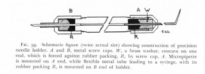
The commercial system provided the microinjection apparatus, shown in fig 10. The microtool was now sealed into a removable tip (apparently a slightly modified non-locking luer tip used in hypodermic needles.) This tried and true system was also much easier to remove from the needle holder. The glass Luer syringe was provided a machined cradle that fastened securely to the base. In the late 1920s, a member of Chambers’ Cornell lab, Dr. Richard Frank’s, devised a ‘precision needle holder’ which was subsequently offered by Leitz. In this arrangement, both the microtool and a brass tube leading to the syringe, were simply inserted into rubber washers at opposite ends of a tool holder. End caps were then screwed over the washers, compressing them and forming a seal without the need for wax or cement. Using Frank’s improvement, a microtool could be replaced in under a minute. [20. Chambers (1929), p. 57., Chambers and Kopac (1950), p. 520.]
Similarly, Dr. William H. Wright, a scientist at the Department of Agricultural Biology at the University of Wisconsin who used the instrument primarily for isolating bacteria, created an extension arm to which the manipulator mechanism could be attached. This permitted a microtool to be efficiently inserted and withdrawn from the moist chamber so that tools could be changed quickly. The instrument was described in 1927 and was produced by Leitz soon after. [21. Wright and McCoy (1927), p. 795]
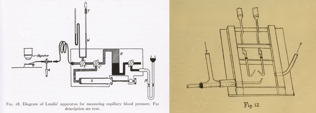
Even while the instrument was becoming standardized through commercial production, new lab-built apparatus were continually being devised for it by a growing community of users. A student textbook from 1931 lists a number of related instruments that had been described in papers over the previous decade. These included a hermetically sealed, nitrogen filled chamber for conducting anaerobic experiments, instruments for measuring pressure in capillary vessels. New microtools included microelectrodes and micro magnets for studying the electrical properties of the cell’s interior, various instruments for performing chemical tests on microscopic particles, micropincers, a microcautery tool and a microguillotine for precisely breaking the tips of fine glass micropipettes. [22. Howland and Belkin (1931) pp. 13-29.]
Conclusion
Reading through the various accounts of early applications of the Chambers’ micromanipulator and its various micrurgical appendages one sees an ambition to develop micromanipulation or ‘micrurgy’ into an significant instrument-based science. Chambers himself once claimed that:
” The science of micrurgy will prove to be a boon to investigators of the microscopic worlds. The new techniques may prove as important to the microspecialist as a pole reaching to the surface of the moon could be to the astronomer.”
In a sense, these ambitions were inherent in his design. Useful though it had proved in exploring the living cell, its adaptability and modularity seemed to promise applications well beyond a particular scientific discipline. In the decades of its widespread use practitioners sought to apply it to a variety of tasks, from the assembly of electronic components to microscopic chemical work. During the Second World War, for instance, micrurgists at the Fairchild Engine and Airplane Corporation used tiny chisels, tweezers, hammers and Magnets under magnification to study the rust that developed on aircraft parts during the American campaign in North Africa. [23. Hildebrand (1960), p. 321.]
Few Chambers’ micromanipulators seem to have survived to the present day—a testament, no doubt, to their technical obsolescence in the face of newer, better automated, designs. Initial enthusiasm cooled as its possibilities and limitations became well understood and the technological cutting edge moved on. Still, its role in illuminating the physical structures of the cell by permitting the scientist to ‘intervene’ in its living functions ought not to be forgotten.
Part two of this post will examine the history of the University of Toronto’s micromanipulator, first as a laboratory instrument, then as a piece of historical material culture. As with all instruments that have outlived their operators, a great deal must be deduced from the physical object itself and from limited evidence concerning its provenance.
[1] Bibliography
Note: For a useful and extensive list of early publications related to micrurgy and the Chambers’ micromanipulator see the bibliography of Howland and Belkin (1931), available here.
Chambers, R. (1918) “The Microvivisection Method.” Biological Bulletin. 34, no. 2. (February), pp. 121-136.
Chambers, R. (1921) “Microdissection Studies, III. Some Problems in the Maturation and Fertilization of the Echinoderm Egg.” Biological Bulletin. 41. no. 6. (December), pp. 318-350.
Chambers, R. (1922a) “New Apparatus and Methods for the Dissection and Injection of Living Cells.” The Anatomical Record. 24. no. 1 (August), pp. 1-19 (contemporary reprint).
Chambers, R. (1922b) “New Micromanipulator and Methods for the Isolation of a Single Bacterium and the Manipulation of Living Cells.” The Journal of Infectious Diseases. 31. no. 4 (October): pp. 334-343.
Chambers, R., (1924) “The Physical Structure of Protoplasm as Determined by Micro-dissection and Injection.” In General Cytology: A Textbook of Cellular Structure and Function for Students of Biology and Medicine, edited by Edmund V. Chowdry, pp. 236- 309. Chicago: University of Chicago Press.
Chambers, R. (1929) “Physical Agents: Microdissection, Mucroinjection.” In Handbook of Microscopical Technique. For Workers in Both Animal and Plant Tissues. (First Edition), edited by Ruth McClung Jones, 39-73. New York: Paul B. Hoeber, Inc.
Chambers, R. and Kopac, M. J. (1950) “Micrurgical Technique for the Study of Cellular Phenomena.” In McClung’s Handbook of Microscopical Technique (Third Edition), edited by Ruth McClung Jones, 492-543. New York: Paul B. Hoeber, Inc.
E. Leitz Inc., New York., (1926) “Pamphlet No. 1066. Dr. Chambers’ Micro-Manipulator: and apparatus for Microtechnique or Micrurgy” E. Leitz Company Trade Literature. (a copy of this pamphlet survives in Countway Medical Library, Harvard Universality, call no. 3.J.1926.1)
Hacking, I. (1983) Representing and Intervening. New York: Cambridge University Press.
Howland, R. and Belkin, M., (1931) Manual of Micrurgy. Ann Arbor, MI: Edwards Brothers, Inc.
Hildebrand, E. M., (1960) “Micrurgy and the Plant Cell.” The Botanical Review. 26. No. 3 (July-September): pp. 227-330.
Wright, W. and McCoy E., (1927) “An Accessory to the Chambers Apparatus for the Isolation of Single Bacterial Cells.” The Journal of Laboratory and Clinical Medicine. 12 No. 8: (May). p. 795.
Images:
Fig 1: E. Leitz Inc, (1926), p. 3./ UTSIC photograph
Fig 2: Chambers (1922a), p. 3./UTSIC photograph
Fig 3: Chambers (1924), p. 268.
Fig 4: Chambers (1919), p. 123.
Fig 5: E. Leitz Inc, (1926), p. 3, 6.
Fig 6: Chambers and Kopac (1950), p. 511.
Fig 7: Chambers (1927), p. 63.
Fig 8: Chambers (1927), p. 52.
Fig 9: Top: Chambers (1927), p. 58. Bottom: Chambers (1921), p. 327.
Fig 10: Chambers (1927), p. 60.
Fig 11: Top: Chambers (1918), p. 126. Bottom: Chambers and Kopac (1950), p. 506.
Fig 12: Chambers and Kopac (1950), 513.
Fig 13: Chambers and Kopac (1950), p. 520.
Fig 14: Chambers (1927), p. 48.
Fig 15: Left: Chambers (1927), p. 67. Right: Howland and Belkin (1931), p. 17.
Notes: