
Fig. 1) Early model of Chambers’ Micromanipulator (c. 1918)

An early shop-built instrument mounted on a narrow, possibly wooden, base. Two micromanipulator mechanisms may or may not be permanently attached to the base. Their position seems to prevent the use of an external microscope illuminator. The cord shown is attached to a microscope light mounted in place of the mirror.
Fig. 2 Microscope-Mounted Manipulator (c. 1922)
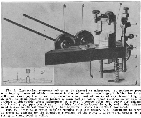
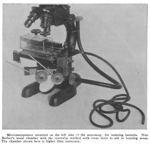
Like earlier instruments by Schmidt and Barber, Chambers’ first micromanipulators that Chambers produced were likely clamped to the microscope stage itself. In his earliest description of the instrument in 1918, Chambers credits another researcher, Dr. H. B. Goodrich of Wesleyan University, for having mounted the instrument on an independent base. No images of this early microscope-mounted instruments seem to have survived in published material, but a later one from 1922, shown here, is probably very similar. At right a similar model is shown mounted to the side for use in isolating bacteria. These would have lacked the stability of the mechanisms mounted to the solid base. It is telling that when the instrument was produced by Leitz, no stage-mounted models were offered.
Fig. 2 Early model of Chambers’ Micromanipulator (c. 1922)
Several new details are apparent in this pre-production version.
– The base has been widened considerably and holes provided for mounting the pillars at the front or sides of the microscope.
– Threaded holes have been drilled around the circumference of the knobs of the manipulator mechanism. Threaded leavers are attached to permit more precise control.
– Flexible shafts have been added so that the rear z-dimension control can be operated from the front of the instrument. This is to prevent accidentally bumping the controls when reaching around to the back. The shaft seems to have been attached to the neck of the microscope.
– This instrument is shown with an early microinjection apparatus. A syringe is held upright in a piece of brass tubing that is clamped to the manipulator base. The illustration at the bottom shows how the tool end of the microinjector is cemented into a glass holder. At the other end, a fine brass tube leading to the syringe is attached. This arrangement, with its multiple glue joints, was prone to leaks.
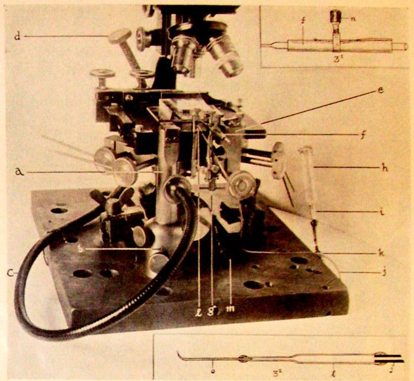
Fig 4. Early Leitz production instrument (c. 1926)

Several changes are apparent in this early production model. In this illustration the microscope and mechanical stage have been obscured to highlight the instrument itself.
– The clamping system for the manipulator pillars and the microscope base have reached a more-or-less final form.
– The ends of the flexible control shafts have been given cradles at the front of the instrument to place them within easy reach of the user.
– A microinjection system (shown in detail at left) has been introduced.
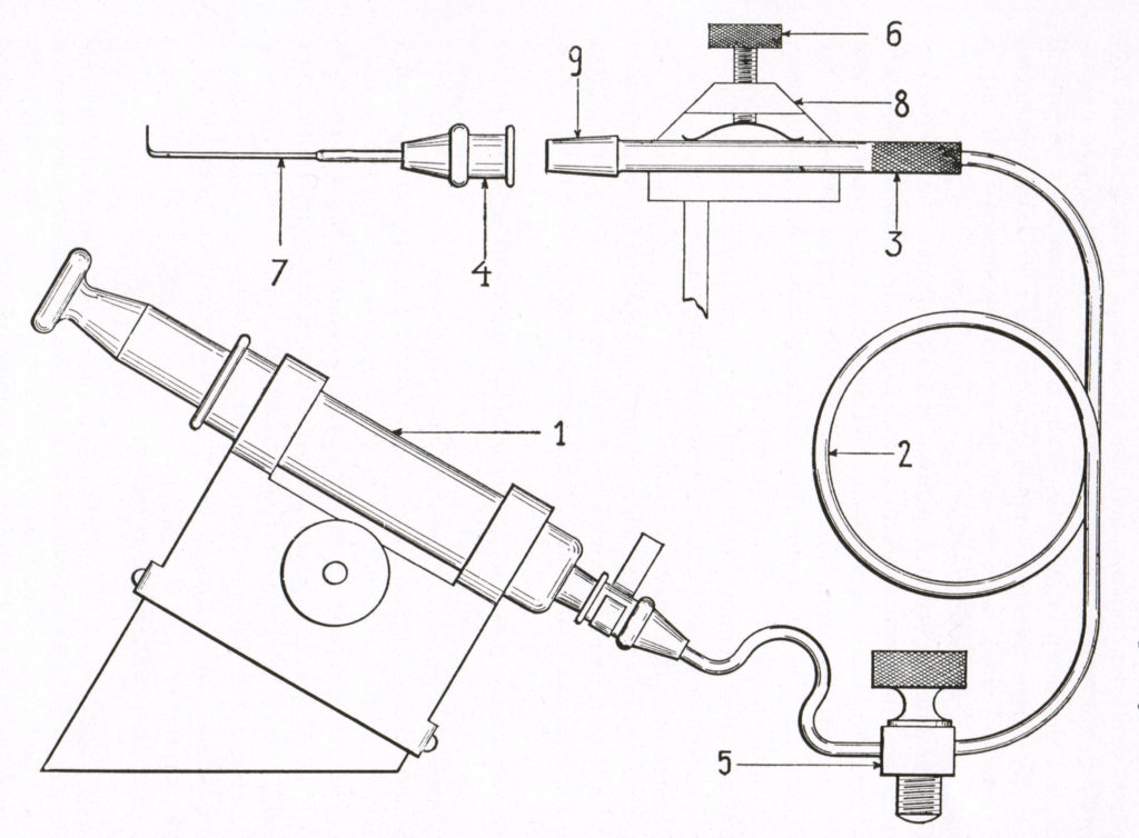
– The syringe is now mounted in a machined holder to steady it.
– Micropipette holder (9) with replaceable Luer tips (4) has been developed. Glass tools (7) may now be more easily removed and replaced.
– A clamp (5) has been added between the syringe and the micropipette holder to make the fine brass tube that connects them easier to manage.
Fig 5. Further Developments
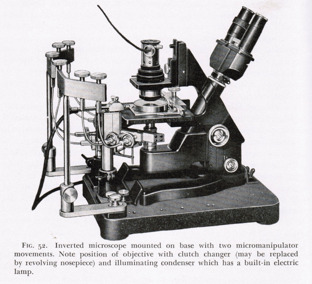
The Chambers’ micromanipulator as depicted in the 1950s (though the illustration may date from a decade or two earlier.) Here all of the manipulator controls are attached to shafts which are mounted on a bracket. The microscope shown here is a Leitz inverted microscope in which the orientation of the objective has been flipped 180 degrees. This permits the sample to be held within a droplet on the floor of the moist chamber rather than suspended from the roof.
Images:
Fig 1: Chambers (1918), p. 126.
Fig 2: Chambers (1922b), p. 336.
Fig 3: Kahn (1922), p. 346.
Fig 4: Leitz (1926), p. 3.
Fig 5: : Chambers and Kopac (1950), p. 506.