
Geophysics Collection · Physics · UTSIC
A large (~64cm x 57cm x 57cm) grey-painted wooden case contains an electrical instrument. The case has two latches on its front face securing its hinged lid and a metal handle on either side.
The instrument within is supported by a circular aluminum plate. Below this, hidden within the wooden case, is an hexagonal electronics enclosure. Above the plate are two fluxgate magnetometer mechanisms oriented orthogonally above the build plate. A variety of cables are attached to the instrument.
Four hold-down plates, labeled “A” through “D”, are located at four points around the perimeter of the mail plate. These are used to secure the instrument to the case for transport. They are attached by wing nut fasteners.
A mainboard, which would normally be mounted to the aluminum plate, is missing. A plastic resealable bag, containing several small screws and plastic washers, is included in the case. These were likely used to mount the missing board to the aluminum plate.
A small circuit board, labelled “OMB Bucking Board” is loose within the case.
Accession Number: 2024.ph.885
Alternative Name:
Primary Materials: Steel, Aluminum, Wood
Outer surface of the case:
Stenciled in black ink on the top and sides of the case lid: “OB M 11” ; Stenciled in black ink on the front surface of the case lid: “11”; Written in small lettering in black ink surrounded by an orange rectangle on the front surface of the case lid: “21091”; Written in large lettering in black ink on the front surface of the case lid: “3”
Inner surface of the case:
Written in black ink on the inner front lip of the lower lid of the wooden case: “SWITCHES OFF?”;
Written along an edge near the hinge on the upper lid: “~[HOLD DOWN BOLTS 10-24”
Case: Height = 64, Width = 57, Length = 57.
This receiver is part of the MOSES (Magnetometric Offshore Electrical Sounding) system used to survey the resistivity of the seafloor by detecting azimuthal magnetic fields at a given point. Properties of the seafloor can be derived from this information.
The receiver consists of two orthogonally arranged fluxgate magnetometers and microprocessor controlled electronics for filtering and digitizing magnetometer readings before recording it to solid-state memory.
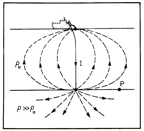
When deployed, the receiver is sealed inside a pressure-tight vessel, attached to a concrete anchor, and dropped from a ship to a point on the seafloor. An electrical current (1.25kw, 25 A, reversing every 4 sec.) is generated by a high-current transmitter powered by the ship’s generator. A wire is suspended vertically below the ship, forming a dipole transmitter with one node on the sea surface and one, from which the current is injected, on the seafloor. Since seawater is highly conductive, most of the current returns to the upper electrode through a direct path. A small portion penetrates the sea floor and returns in a circuital path.
The principle of operation is described as follows: “The current injected returns to the sea surface via axially symmetric flow lines. The azimuthal magnetic field generated is proportional to the sea-crust resistivity contrast since the field measured at the sea floor is proportional to the current flow enclosing the field point.” (Nobes 1984, 6, illustration from Edwards et al. 1984, 154)
During a survey, the research ship with the suspended transmitter cable travels relative to the receiver’s fixed location creating a range of horizontal transmitter-receiver separations. The receiver measures the strength of the azimuthal magnetic field that has entered the sediment. The location of the ship and its position relative to both the transmitter electrode and the receiver on the seafloor is tracked using radio transponders.
When the sounding process is complete, the receiver’s pressure vessel is released from the concrete anchor and recovered from the surface with the aid of a radio beacon. Data is downloaded from the receiver to floppy disk for computer processing.
The case is intact but heavily worn with evident damage at points along the bottom edge. The metal hinge and latches are rusted. There are various patches of old adhesive on the outer surface of the case.
The instrument is in good cosmetic condition, though incomplete. It is notably missing a main electronics board. Silver duct tape, used to secure plastic covers at either side of each magnetometer mechanism, is peeling away.
Associated Instruments:
University of Toronto Department of Physics machine and electronics shops.
Date of Manufacture: c. 1984.
This artifact is part of a small collection gathered from the office of Prof. Nigel Edwards of the University of Toronto Department of Physics in March of 2022.
Richard Nigel Edwards, Lawrie K. Law and J. M DeLaurier (1981) “On Measuring the Electrical Conductivity of the Oceanic Crust by a Modified Magnetometric Resistivity Method.” Journal of Geophysical Research 86, no. B12 : 11609–15.
Edwards, R. N, D. C Nobes, and E Gomez-Trevino (1984) “Offshore Electrical Exploration of Sedimentary Basins; the Effects of Anisotropy in Horizontally Isotropic, Layered Media.” Geophysics 49, no. 5: 566–76.
David C. Nobes. (1984) The Magnetometric Off-Shore Electrical Sounding (MOSES) Method and Its Application in a Survey of Upper Jervis Inlet, British Columbia. PhD Thesis. Toronto, Ontario : University of Toronto.
Peter A. Wolfgram. (1985) Development and Application of a Short-Baseline Electromagnetic Exploration Technique for the Ocean Floor. Toronto, Ontario : University of Toronto.
Richard Nigel Edwards, Lawrie K. Law, P. A. Wolfgram, D. C. Nobes, M. N. Bone, D. F. Trigg, and J. M. DeLaurier. (1985) “First Results of the MOSES Experiment; Sea Sediment Conductivity and Thickness Determination, Bute Inlet, British Columbia, by Magnetometric Offshore Electrical Sounding.” Geophysics 50, no. 1: 153–60.
Steven Constable (2010). Ten years of marine CSEM for hydrocarbon exploration. Geophysics, 75(5), 75A67-75A81.
Seafloor EM research emerged, in part, from research done at Scripps done by researchers including Charles “Chip” Shipley Cox (1922 -1915) in the early 1960s. This was reportedly based on defense-funded research conducted in search of a method for communicating with military submarines in the event that radio communication was disrupted by a nuclear war. Early unclassified and published work in this area is described in Constable 2010.
The MOSES system emerged from earlier work on the Scintrex MFM-3 High Sensitivity Vector Fluxgate Magnetometer. The MFM-3 was developed in the early 1970s by Harry Siegel and Nigel Edwards. The latter worked at Scintrex prior to taking a faculty position at the University of Toronto. The MFM-3’s sensor incorporated an amplification system developed in Germany during the Second World War for use in magnetic anti-shipping mines. This resulted in a very compact and sensitive sensor suitable for measuring alternating magnetic fields.
The MFM-3 was used by Harry O. Siegel (1924 – 2011) to record magnetic fields induced by currents passing through the earth with the goal of identifying mineral deposits. This groundbreaking MIP (Magnetic Induced Polarization) method and MFM-3 instrument are described in Siegel 1974. The MFM-3 sensor component (and hence MOSES receiver) contains some of the earliest operational amplifiers ever made.
According to Nigel Edwards, the MFM-3 was not especially effective in terrestrial applications and did not become a commercially successful instrument. The MOSES receiver was developed by Nigel Edwards to apply this technology to undersea EM research where it was particularly suitable for detecting the time-delayed return signal passing through the restive seafloor. The theory behind the MOSES system was introduced in Edwards, Law, and DeLaurier 1981 and Edwards, Nobes, and Gomez-Trevino 1984.
The MOSES receiver incorporates two MFM-3 sensors in a perpendicular orientation to measure the horizontal component of the induced magnetic field produced by a dipole electrical transmitter suspended from a ship. Rather than being attached to a control box, the sensors are linked to a custom-designed computer control board that records data automatically when the receiver is on the ocean floor. The board was designed at the University of Toronto Department of Physics electronics shop.The sophisticated transmitter used in the MOSES system was designed by Dr. Shashi B. Dewan (1940-2009), Professor of Electrical Engineering at the University of Toronto.
A number of test surveys to inlets in coastal British Columbia took place over the early 1980s. Initial problems included the tangling of transmitter cables. This was solved using a specialized winch and hanging the cable rather than lowering the cables to the bottom. The first interpretable results were obtained in a survey in Bute Inlet, BC. using the Canadian survey ship Vector captained by R. W. MacKenzie (See Edwards et a. 1985). A subsequent survey done in Upper Jervis Inlet is described in Nobes, 1984. Experiments using the MOSES system to study subsea permafrost thickness were conducted by then PhD student Peter A. Wolfgram in the Beaufort sea.
Around three MOSES receivers were built. This is the only surviving example.
The MINI-MOSES system, an elaboration of the MOSES approach, is described in Peter A. Wolfgram (1985).