
This artifact consists of two primary components: an outer “can” housing (2021.ph.860.1) and an inner “cell” (2021.ph.860.2).
2021.ph.860.1– The “can” is a heavy steel component consisting of a sturdy cylindrical housing mounted to a square aluminum base. It is a pressure vessel that is filled with temperature controlled, pressurized water when the instrument is in operation. The cylindrical housing is surrounded by a water jacket and is secured to the base with four threaded feet used to level the apparatus. The jacket has copper inflow and outflow ports on its top and bottom edges. An electrical cable and a serial data cable exit the can from the bottom of the cylinder.
At the top of the housing is a metal flange with a transparent window at its centre. A series of bolt holes around its circumference permit the lid to be secured to the housing. Two ports, one larger than the other, extend from the top of the flange. These serve to degas and debubble the cooling water.
Beneath the lid is the cavity into which the inner cell is inserted. Electrical leads can be seen within the cavity. These connect to electrical components within the cell described below. Around the perimeter of the cavity is a series of holes. When the instrument is in use, these holes direct the flow of water over the lid of the cell and return it to a water pump beneath the cavity.
2021.ph.860.2 – The “cell” is a cylindrical element with sapphire window at the top that corresponds to the window in the lid of the can. This window has a reflective appearance due to the reflective aluminum plate just below it. The sapphire window and bottom plate form a chamber less than a millimeter tall. When the instrument is in operation, this chamber contains pressurized CO2 gas. The perimeter of the top surface contains a series of holes and black plastic guides. These direct a flow of pumped water within the “can” housing over the chamber in order to equalize temperature over its surface. They also permit the water to return to the pump that is located in the can.
Several electrical leads exit the bottom surface of the cell. These attach to the corresponding leads within the can. They belong to the three piezoelectric actuators and a heater below the bottom plate of the chamber.
Accession Number: 2021.ph.860.1-2
Alternative Name:
Steel, Aluminum, Single-Crystal Sapphire
Markings:
2021.ph.860.1 Height = 65, Length = 30, Width = 30
2021.ph.860.2 Height = 9, Max diameter = 15.
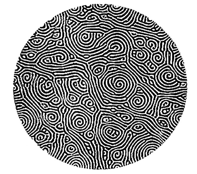
This apparatus was built to observe thermally-driven convection patterns in hot pressurized gas. It employed carbon dioxide and typically operated at a pressure range of 300-400 psi. It was used in the discovery of a non-linear pattern known as “spiral defect chaos”. An image of this pattern is provided in Morris et al. 1993 p. 3:
The apparatus uses carbon dioxide contained within a sub-millimeter gap between two plates. The top plate, consisting of transparent single-crystal sapphire, serves as a window through which to observe convection patterns in the gas. The mirror-polished bottom plate is made of diamond-machined aluminum. These plates are kept highly parallel through a leveling mechanism consisting of adjusting screws for coarse adjustments and three piezoelectric actuators for fine adjustments. The level is verified using by laser interferometry using a separate instrument that was developed alongside this apparatus. A slight temperature difference between the heated bottom plate and the slightly cooler top plate produces the convection patterns.
This cell is contained within a “can,” a pressure vessel that established and maintained the pressure and temperature of the cell by circulating temperature controlled, pressurized water around it using a water pump. The can exterior is temperature regulated using a water jacket. The instrument may operate continuously for weeks at a time under the control of a computer.
Convection patterns in the chamber were imaged using a shadowgraph and CCD camera that observed the cell through sapphire windows in the can and cell. These imaging components of the instrument have not been preserved.
The instrument is in working condition but is missing its shadowgraph imaging apparatus. It has signs of wear and use, but no major damage.
Associated Instruments:
University of California, Santa Barbara Physics Machine Shop
Date of Manufacture: 1991
This instrument was made in the Machine Shop of the Department of Physics at University of California, Santa Barbara in early 1991. It remained in use there for numerous experiments, possibly as late as 2009. It was sent to Professor Stephen Morris at the University of Toronto around 2010.
This artifact was donated to the UTSIC project of the IHPST on Wednesday, October 27, 2021, along with a second cell belonging to a slightly earlier version of the experiment.
John R. de Bruyn,, Eberhard Bodenschatz, Stephen W. Morris, Steven P. Trainoff, Yuchou Hu, David S. Cannell, and Guenter Ahlers. “Apparatus for the Study of Rayleigh–Bénard Convection in Gases under Pressure.” Review of Scientific Instruments 67, no. 6 (1996): 2043–67. https://doi.org/10.1063/1.1147511.
Stephen W. Morris, Eberhard Bodenschatz, David S. Cannell, and Guenter Ahlers. “Spiral Defect Chaos in Large Aspect Ratio Rayleigh-Bénard Convection.” Physical Review Letters 71, no. 13 (1993): 2026–29. https://doi.org/10.1103/PhysRevLett.71.2026.
The original experimental movie, filmed in 1992 using this instrument, is available on YouTube. (Accessed Nov 17, 2021)
Prof. Morris also donated several folders containing photocopied engineering drawings related to the instrument and related apparatus. These have been archived by the UTSIC.
The primary significance of this instrument is its role in the discovery of the phenomenon of the “spiral defect chaos” pattern. These were observed in a type of convection known as Rayleigh–Bénard convection within a chamber of pressurized CO2 gas. The chamber was imaged using a shadowgraph instrument that reveals heat patterns. This was a surprising and important discovery as this dynamic, chaotic pattern appeared under circumstances at which existing models predicted a non-chaotic “straight-roll” pattern.
The apparatus was built at the machine shop of the University of California, Santa Barbara Department of Physics for the postdoctoral research of Stephen Morris. It followed an earlier instrument of similar construction, but featured differences in cell design that, along with changes in experimental design, permitted the spiral chaos pattern to be observed. Such instruments were extremely challenging to build, mostly due to the precision machining and welding required to contain the highly pressurized water. The top and bottom surfaces of the cell also had to be extremely parallel and flat for the Rayleigh–Bénard convection patterns to be observed.
Both the apparatus design and the observation of the spiral chaos pattern proved important contributions to nonlinear physics and pattern formation. Both produced widely cited papers (see de Bruyn et al. 1996 and Morris et al. 1993). Further apparatus of this type were built on this pattern at sites including Cornell University, the Max Planck Institute, Göttingen, the Los Alamos National Laboratory, University of California, Santa Barbara, and Memorial University, Newfoundland.
Although this apparatus was built and operated at the University of California, Santa Barbara, its significance extends to the University of Toronto. Notably, the identification of the spiral chaos phenomenon led to the recruitment of Professor Stephen Morris by the University of Toronto Department of Physics in 1993. While in Toronto, Morris operated the experiment remotely using Telnet to control the apparatus and an FTP server to download images from the integrated CCD camera—a noteworthy use of the early internet.
This form of experiment was actively pursued for several years after this instrument was built. More recently, the ever-increasing power of computers has meant that digital simulations have tended to replace physical apparatus such as this one within the domain of non-linear physics.
Models
- Donated to UTSIC